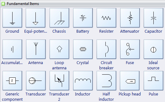
. Built-In Electrical Design TemplatesDozens of electrical design templates will help make you instantly productive. Choose a template that is most similar to your project and customize it to suit your needs. Smart FormattingSmartDraw's electrical symbols connect to circuit lines automatically. To add a symbol to your electrical design, all you have to do is drag a symbol to a line and drop it. The line will split into two and connect each end to the symbol in exactly the right place.
The symbol will stay attached even when you move the line around. Free SupportGot a question? Call or email us. SmartDraw experts are standing by ready to help, for free!
Autocad Electrical Single Line Diagram
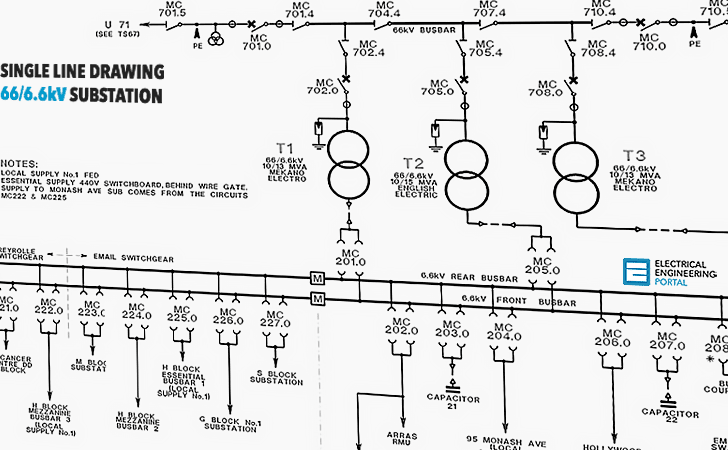
. Single-line diagram is a simplified notation for representing a three-phase power system; Instead of representing each of three phases with a separate line or terminal, only one conductor is represented. Electrical elements such as circuit breakers, transformers, capacitors, bus bars, and conductors are shown by standardized schematic symbols. Elements on the diagram do not represent the physical size or location of the electrical equipment.

Single Line Diagram Software

On one-line power diagrams, components are usually arranged in order of decreasing voltage levels. The highest voltage component is shown at the top right of the drawing.
In order to find out how power is supplied to a component, start at the component and trace the flow of power backwards through the drawing. This method will be most useful in locating the correct circuit breaker to isolate a component for maintenance. You can read the single line diagram from the top to the bottom or from left to right of the diagram. Manufacturers type designations, and ratings of devices. Ratios of current and power transformers, taps to be used in multi-ratio transformers, and connections of double-ratio transformers. Rating connections of wye and delta power transformer windings. Circuit breaker ratings in volts and amperes.
The interrupting rating, type, and number of trip coils on circuit breakers. Switch and fuse ratings in volts and amperes. Function of relays. The sizes, type, and number of incoming and outgoing cables. The voltage, phase, and frequency of incoming and outgoing circuits. The available short circuit and ground currents of the power company system, and type of ground used. Metered points and type of metering.
The amount of the load on all feeders. Compare the calculated “first cycle” (Momentary) asymmetrical current duty with the close and latch circuit breaker capability. Compare the calculated “1-1/2 to 4-cycle” (interrupting) current duty with the circuit breaker symmetrical interrupting capability. (as per ANSI C37.010: Application Guide for AC High-Voltage Circuit Breakers Rated on a Symmetrical Current Basis). Determine the applicable circuit breaker ratings. Compare the feeder cable short-circuit heating limit with the maximum available short circuit current time Kt times Ko. (See IEEE 242-1975: IEEE Recommended Practice for Protection and Coordination of Industrial and Commercial Power Systems).Note.
The calculations performed in accordance with Reference to (ANSI C37.010: Application Guide for AC High-Voltage Circuit Breakers Rated on a Symmetrical Current Basis) determine only medium and high-voltage circuit breaker ratings. Perform short-circuit studies to determine relay operating currents in accordance with procedures outlined in IEEE 357-1973: IEEE Guide for Protective Relaying of Utility-Consumer Interconnections). For other than power circuit breakers, refer to the appropriate ANSI standard for short-circuit calculation procedure.2- Partially Developed One-Line Diagram. Show all relaying, instrumentation, and metering. Select relaying, instrumentation, and metering.
Confirm the selection of relay ratings and characteristics by performing a complete system short-circuit and coordination study.